by Olivia S. Chaves and Fabio M. Rossi – Exchange Students in Ship Design / Høgskolen i Ålesund
(oliviachaves@poli.ufrj.br/fabiorossi@poli.ufrj.br), v2, Dec 2014.
[toc]
Introduction
A modular design consist in dividing complex systems in smaller ones, so that is easier to handle them separately. Dividing the system in modules is not only helpful for dealing complexity, but also enables parallel work and promotes innovation. The reason behind it is that modular systems have standard interfaces, which guarantee that the module can be designed independently, and afterwards they will fit each other and compound the whole system.
In addition, having a system divided in modules might give us some freedom in assembling these modules. For example, since the interfaces are standard, a supposed A-module might complement a B-module, as well as a C-module. In this way, it is possible to produce a wide variety of outcomes (assemblies) from a single range of modules.
In doing so, if we take an Offshore Support Vessels (OSV) as our system, we can apply this approach in many different ways. The criteria used to divide a vessel in sub-systems might be, for instance, structural, piece size, or even construction phase.
After dividing OSV in modules and assembling them, we obtain a vessel with unique characteristics that will perform some missions better than others. Therefore, we can say that a given assembly is better than another one for performing a given mission by evaluating which modules it contains.
Afterwards, a Graph User Interface (GUI) is proposed in order to evaluate how prepared a given assembly is for performing a mission. The GUI main goal is that the user can to choose the ship’s features he/she would like to implement on the ship’s design, and in the end a grade is given for the set of choices.
Methodology
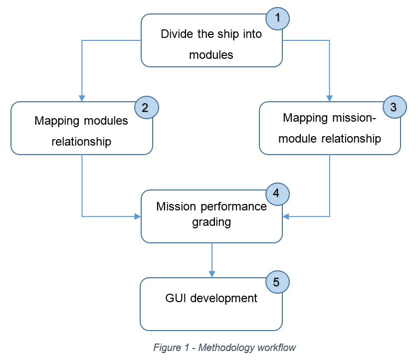
First, we have simply divided an OSV in modules, where we used a functional criteria to do so. Then, we have evaluated the relationship among these modules and a given mission, and how these modules interact with each other as well. Then, an GUI started to be elaborated. The GUI gives an idea about how modules and evaluation might be handled.
The methodology workflow is:

Where each step means:
1. Divide Ship into Modules
This consist in spliting interconnect systems, and group them according to some rule. Having these sub-systems organized in groups means having a modular ship division.
The ship division was made in a preliminary way, according to system’s functionality, where all systems related to the same function should belong to the same module.
2. Mapping Modules Relations
Consist in describing how the modules interact with each other. “The mapping” first approach was basically to write down suggestions about how the modules obtained on the first step might influence each other.
3. Mapping Mission-Module Relationship
Consist in assessing how required each module is in a ship that should perform a given mission. This is related with the role that each module plays when the ship is operating a mission.
4. Mission Performance-Grading
The mission performance-grading phase consists in giving a value for an assembly (arrangement of modules) considering the mission that the vessel should perform. It is made through a GUI that assists the user in choosing the ship’s features that he/she would like to implement in the design.
Simple Case
Applying the methodology we have proposed, for instance, we have the following:
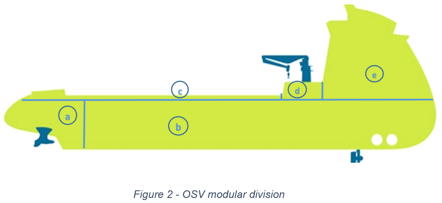
1. Ship division:

Where we have: (a) Propulsion, located in the stern, (b) Tank/cargo hold, at the middle (square body) and in the bow, (c) Main deck, (d) Crane, and finally (e) Accommodation, in the deckhouse located aft bow.
2. Modules Relationship:
3. Mission-Module Relationship:
4. Mission performance-grading:
In the mission performance grading, the value we will give is measured through numbers. The tool used to calculate this grades is a GUI that enables the user to choose vessel mission and some of its features. Inside the GUI there are formulas that automatically release the grade for a chosen assembly, formulas which were elaborated considering the notes presented in the matrix from step 4. However, for now, the numbers used have no theoretical basis and are just illustrative.
The GUI might be seen in the following video:
Further Steps
Now, our intention is to develop this work towards a grounded and precise grading system. In order to do that, our aim is not only have ship modules imported from Simens NX and displayed in our GUI, but also parameterize these modules and import its properties/attributes to use as calculation source. Therefore, grading the assemblies can be done according to modules attributes (structural, hydrodynamic and functional properties) in a more precise way, even if user changes any ship dimensions, which he/she is allowed to do.


