by Sthéfano Lande Andrade – MSc Student in Ship Design / Høgskolen i Ålesund
(sthefano.lande@gmail.com), v1, Oct 2014.
The objective of this report is to create one method that can be used to generate parametrized structural elements from a hull design. To achieve this goal the NX program from Siemens will be used. The input will be a simplistic version of a hull, also designed using NX, but having its main dimensions already defined.
Flowchart
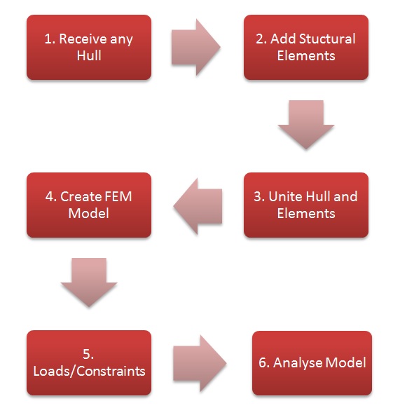
The following flowchart presents the main steps of the creation process of structural elements and the analysis using the NX program from Siemens.

Workflow chart
Each step will be explained more thoroughly next:
1. In this step a bare hull is received from an external creator. The hull will have each of its main characteristics, as length, depth, beam, bilge radius, associated to a variable.
2. Having the hull form and dimensions, then it’s possible to create the structural elements. To effectively achieve that, it’s necessary to use rules determined by a classification society and apply those rules according to vessel type and the hull. It’s actually challenging to parametrize the structural rules given by a classification society, however the concept can be tested through a simplistic approach. In this case the analysis will focus solely on the bulkheads creation.
3. The structural elements and the hull should be then joined together as a whole entity to prepare for the next steps.
4. This whole entity then will be meshed using Finite Element Method (FEM) function available in the NX program and the material characteristics added to the model.
5. Then model must then be restrained and pressure added to its surface, which will represent the hydrostatic pressure and the forces caused by the modules that will be installed on it.
6. Finally, a simulation will be run, the results must be analysed and a the viability of the hull is determined.
It’s worthy to add some observations that involve those steps. The first being about the meshing of the model, which must be done with caution or the runtime can become excessive. Also, the model can have different materials in its final form, since the use of high tensile steel in some regions might be necessary. Finally, these steps represent the concept of the method and there are different approaches that will result in parametric structural elements, the following method is just a concept proof a simple hull.
Creating the Bulkheads
The following section contains the tutorial explaining how to replicate the method used to create parametrized bulkheads in NX.
Video Tutorial:
Analysing the model using Finite Elements Method
This tutorial will teach how to perform a FEM analysis to the body created previously:
Video Tutorial:
The tutorial can be summarized into steps that should be followed in other to prepare and perform a finite elements analysis.
First it’s necessary to create the finite elements, which can be one, two or three dimensional, depending on the model drawn, and the user must choose the size of the elements keeping in mind that, the smaller the size, the better is the discrimination, but the computer will take a longer time to calculate the results.
The next step is to assign the materials properly to the elements. Then the boundaries are defined, the user needs to choose the right constraints to perform a static analysis representing the phenomenon properly. A motion analysis can be performed as well, but the right choice of boundaries are still required. Also, the user need to verify the contact between the different meshes, which will permit the stress to be propagated between the elements.
Then a force/load/pressure is assigned to specific regions, which will represent the environmental/ work conditions of the system. There might be different scenarios and it’s necessary to define each ones are critical and must be solved.
After the model is solved, the operator must understand the results. It’s not enough to assume that the answer printed by the program is the only and final one, it’s the engineer job to understand the results and come with a better design, more cost effective or correcting mistakes that might occur.
Result Example
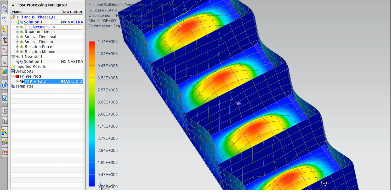
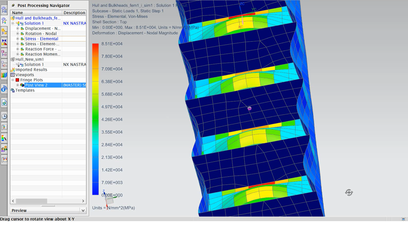
After following the steps described in both tutorials and solving the model the following solution can be obtained.
 Structural Displacement Simulation
 Structural Stress Simulation
Video: FEM Analysis Results
The Finite Elements Method doesn’t require separate analysis for global and local stresses, the benefit of this method is that it’ll take into consideration all the interactions between structural elements and show the final combined stress. The limitation of the results obtained by the method is directly related to the size of the mesh and the processing power of the computer. However, the results must be studied both locally and globally, because the ship has a whole might be able to withstand a certain stress, but the locally would produce a rupture and break the water-tightness the structure.
Final Consideration
The advantage of this approach is that simple changes on the main parameters of a hull won’t require the model to have its structural elements and modules to be manually updated, thus reducing the amount of man hours necessary to finalize the project.
However, the feasibility of the method has not been tested with all the structural rules required by the classification societies, which could prove to be a challenge.
The next step would be the application of the same steps, but applied to a realistic hull, imported from a specialized designing software as Maxsurf, and insert to it structural components as girders, bulkheads, keel etc. following a classification society rule.
